8+ grease trap diagram
Shop The Official HD Supply Site Today. Once youve removed the lid take note of where each part of the grease trap is located.

Schematic Installation Of Grease Trap Effluent Filter Download Scientific Diagram
25 GPM Grease Trap CAD Drawings Zip.

. The result would be grease buildup downstream defeating the purpose of the interceptor. 45 2038 6995 1b ovn 7167 lbVu Min Sti 017 in2 2121 Maple Road Joliet IL 60432 Phone Fax Use Long Span. Nathaniel Whiting obtained the first patent in the late 1800s.
Click to download files. Kim McDonald ReWa 864-419-7251 or Keith Moore ReWa 864-419-7051 Note. In general grease traps range from a minimum capacity of 28 m3.
Insert two supplied 14-20 x 58-inch phillips truss head screws into nut inserts and start the threads. 20 GPM CAD Drawings Zip file. Incorporated into grease trap design.
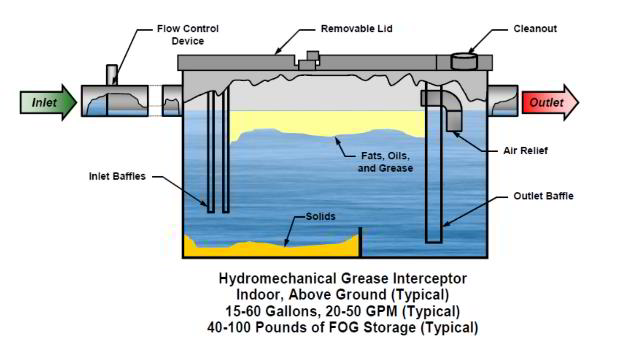
CAD Drawings for Grease Traps. Creating a grease trap diagram can help you keep track of the traps. Grease traps are designed to stop fats oils or grease from entering the sewer lines.
The traps reduce the amount of fats oils greases and solids FOGS that enter. Shop The Official HD Supply Site Today. The Grease Trap Schematic Table 1 The initial characteristics of the wastewater sample taken at the Padang Cuisine Restaurant in Surabaya.
Ad Sign In Now And Start Saving. The size of the grease trap depends on the anticipated flow rate water temperature and grease concentration. 15 GPM CAD Drawings Zip file.
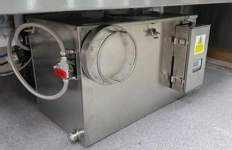
Get Your Supplies From The Industry Leader In Facility Maintenance. ReWa Grease Interceptor Detail QUESTIONS. 4 shows how the Grease Trap was designed.
Parts List per diagram. The standard grease interceptor shall be constructed with a minimum of two baffles. Position grease trap hooks over the screws and tighten.
If left unchecked fats oils and grease solidifies and sticks to the insides of the pipes trapping food. Create a grease trap diagram. In this case the outlet line itself shall have a two inch vent.
Not to scale 24-inch opening to accomodate a 24. Grease interceptors are to be installed at a distance of 8-10. M10482 For those grease traps having a gasketed cover the grease trap outlet line shall not be allowed to be inter- nally vented.
7 GPM CAD Drawings Zip file. If you think all video information are worth for you just have to pay for coffee to support channel httpswwwpaypalmeafreenaliGrease Trap Fat Trap ins. Grease traps have been used since Victorian days.
Grease traps Grease Trap grease trap pumping grease traps cleaning Grease Trap RepairFree Estima. Ad Sign In Now And Start Saving. The unit before proper separation can be achieved Diagram C.
Get Your Supplies From The Industry Leader In Facility Maintenance.
What Is A Grease Trap How Does A Grease Trap Work Aqua Cure

Grease Trap Pit Plan Detail Dwg File How To Plan Grease Traps
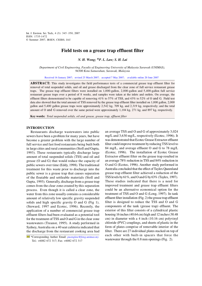
Schematic Installation Of Grease Trap Effluent Filter Download Scientific Diagram
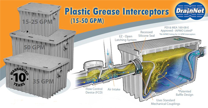
Grease Traps Standard Sizes

Cross Section Of Typical Grease Interceptor Download Scientific Diagram

Portable Hand Wash Foot Operated Junior Buy Online Ireland Commercialsinks Ie
Schematic Installation Of Grease Trap Effluent Filter Download Scientific Diagram

Transition Metal Carbide Complexes Chemical Reviews

Rules Elliot Negelev
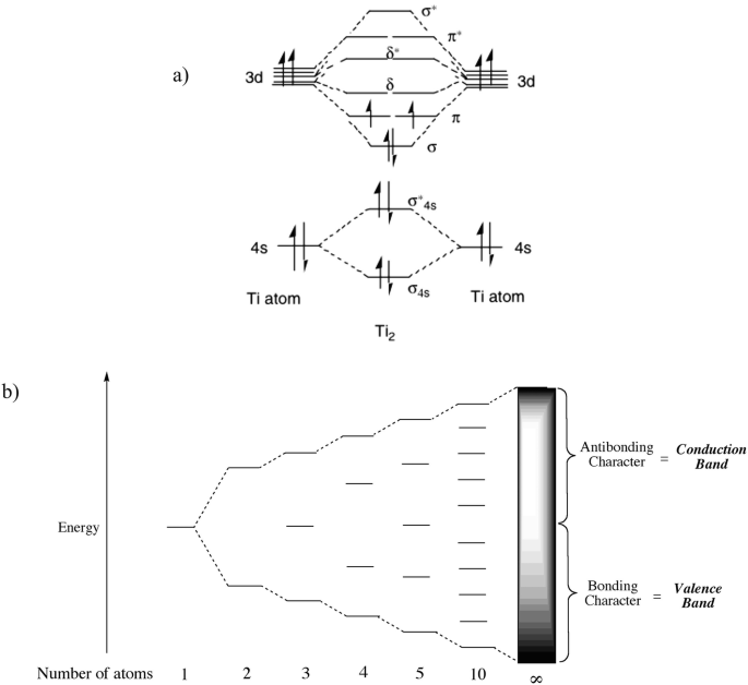
Solid State Chemistry Springerlink

Schematic Installation Of Grease Trap Effluent Filter Download Scientific Diagram
Vacuum C Hi Res Stock Photography And Images Page 5 Alamy

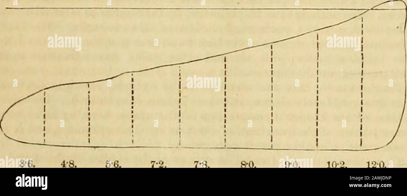
Ecological Dimensions Of Towns Part Ii Towns Ecology And The Land
Grease Interceptors Grease Traps Grease Trap Types Specifications Sources Installation
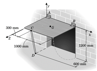
Chapter 3 4 Problem 84p Bartleby

Versatile Coordination Chemistry Towards Multifunctional Carbon Nanotube Nanohybrids Guldi 2006 Chemistry A European Journal Wiley Online Library

A Schematic Diagram Of A Traditional Grease Trap Two Chamber With 1 Download Scientific Diagram